[vc_row][vc_column][vc_column_text]
Surfside Champlain Towers South Condominium Collapse and Condition Assessment of Nearby Aging High-Rise Buildings from a Corrosion Engineering Perspective
Mehrooz Zamanzadeh, Ph.D. George T. Bayer, Ph.D., Edward S. Larkin, Anil Kumar Chikkam, and Peyman Taheri, Ph.D.
Matergenics, Inc.
100 Business Center Drive
Pittsburgh, PA 15205
(412) 788-1263
www.matergenics.com
and
William Clayton, Esquire
Clayton Trial Lawyers, PLLC
401 E Las Olas Blvd, Suite 1400
Fort Lauderdale, FL 33301
(954) 712-2300
www.ctllawyers.com
July 27, 2021
Summary
Routine corrosion risk assessments performed by NACE-certified corrosion experts are an invaluable asset to owners of aging concrete structures. Not only do they identify corrosion risk, but they can also quantify the severity of corrosion and offer remaining life estimates and corrosion mitigation strategies to prolong the life of these structures at much lower cost than total replacement. Based on our years of experience, current codes for construction and inspection are not adequate from a corrosion engineering perspective because they do not consider quantitative corrosion risk assessments. The 40-year recertification cycle has failed to account for this disaster. The time between certifications should be based on the corrosivity of the environment and results from previous inspections. Identifying corrosion is only the beginning; determining its severity and responding immediately can prevent disasters and save hundreds, or even thousands, of lives.
In this paper, we discuss the possible reason(s) and factors contributing to the Champlain Tower collapse in Surfside, Florida. This discussion includes recommended practices for corrosion risk assessment of nearby aging buildings.
There were reports as early as 1996 of extensive water damage and accelerated corrosion in the pool deck and parking garage of Champlain Tower. The pool deck did not have a slope for water drainage. Entrapped pools of water were always observed on both the pool deck and parking garage areas. Spalling of concrete was observed everywhere in the building including the garage slab, indicating accelerated corrosion of rebar due to rainwater exposure. This rainwater picked up chloride ions that had been deposited on external surfaces and was entrapped and concentrated on the pool deck. The saltwater penetrated the concrete and cracks in the pool deck, causing accelerated corrosion of the steel reinforcement and weakening the structural concrete. The disaster was decades in the making. Possible saltwater sources should be investigated by analyzing corrosion products and corrosive ions inside the concrete cores for both pool deck and garage concrete in suspected areas that entrapped water, and exhibited extensive damage, cracking and spalling. There was extensive cracking in the pool deck and garage foundation. The best explanation for how the slab fell down, with the columns punching through, may be that the top layer of rebar corroded, spalled the concrete and disbonded the top 2.5 inches of concrete from the rest of the slab! Concrete petrographic analysis should be performed to determine the integrity of concrete in both slabs. Replacement was likely indicated because of the cumulative deterioration: there is a record of 1996 repairs prior to the 2018 inspection, just before the required 40-year inspection. Lack of knowledge of corrosion control techniques contributed to the collapse and failure of the aged building. No corrosion engineers were engaged in the condition assessment or engineering solution.
The following inspection and condition assessment procedures should be performed immediately on similar aging buildings/structures in nearby ISO 12944 C5 and marine environments:
- Pre-assessment: desk study, ground movement, and GIS corrosion mapping of the site.
- Condition assessment, visual inspection, and corrosion mapping by half-cell potentials.
- Identification of high corrosion risk sites.
- Direct and focused condition assessment of high-risk corrosion areas.
- Thickness loss measurements in rebar and load-bearing members.
- Quantification of risks by existing structural models.
- Engineering recommendation: repair, replacement, or no action.
- Cathodic protection and coating, if feasible, after structural repairs.
- Corrosion monitoring by wireless sensors.
Case histories will be provided for similar buildings in other locations studied by the authors. The authors will also provide guidelines on how to protect the corroded reinforcements with engineering solutions that are not as costly as replacement. More likely than not, the repair cost estimates based on replacement prevented timely attention to this critical task, contributing to the collapse of the Surfside condominium.
In conclusion, corrosion risk assessment of load-bearing members and reinforced concrete early on by NACE-certified corrosion engineers may have prevented this catastrophic failure. The 40-year re-certification cycle has failed to account for this disaster. The time between certifications should be based on the corrosivity of the environment and results from previous inspections. Identifying the corrosion risk is only the beginning; determining its severity and responding immediately can prevent disasters and save hundreds, or even thousands, of lives.
This paper is a preliminary review of the possibility of collapse caused by corrosion and its impact on the steel reinforced structural elements within the building. The collapse of the Champlain Towers South Condominium in Surfside, Florida may have been caused by deterioration of the reinforced concrete over time, inadequate design, workmanship, faulty repairs, stress overload, or accelerated corrosion due to chlorides in a marine C5 environment. One or more combinations of these factors could have resulted in the progressive failure and eventual collapse of the building. Corrosion is a life limiting mechanism for aging structures. In this paper we will discuss the possible mechanisms for collapse of the Champlain Towers South Condominium from a corrosion engineering perspective. The potential for failure from a corrosion point of view has not been widely discussed in the media coverage of the collapse. Not all pertinent photographs or building materials have been examined to a reasonable degree of engineering certainty. Accordingly, this document is subject to change, clarification, or amendments as other material information may be discovered and presented in the future.
Introduction
High-rise building failures and total or partial collapses of condominium complexes are nightmares that haunt the construction industry and architects. The loss of life, the financial devastation, and the anxiety experienced by the architects and tenants in nearby buildings makes for sleepless nights.
In this article, we will discuss and address aging high rises, corrosion risk assessments in corrosive environments, how to determine if a building has unacceptable corrosion risks, and low-cost engineering solutions to implement if the risks are identified in a timely manner.
The disastrous collapse at the Champlain Towers South Condominium in Surfside, Florida on June 24, 2021, was assessed by employing corrosion engineering principles, and considered to be the result of corrosion of the building’s lower level. This corrosion was likely accelerated and caused by the salt deposition and increased duration of wetness on the pool deck, as well as by the water flooding the lower level of the parking garage. No corrosion protection was in place, cover concrete on the rebar was shallow, and according to tenants, corrosive saltwater exposure had been taking place for years. Water corroded the steel reinforcement, reducing the thickness of these support members and initiating the progressive failure of the concrete. Photographs from the site show extensive spalling concrete on the rebar in the garage area. A structural engineer’s report in 2018 found failing waterproofing on the pool deck area, and residents complained of longstanding flooding in the garage.
The videos in media do not show much spalling except on the pool deck, in the pool equipment room, on the balconies, and on several columns in the parking garage. As spalling accompanies corroding rebar, there is not extensive evidence at this time of extensive corrosion of the rebar. Did the 1996 repairs and repairs in the parking garage hide the accelerated corrosion of reinforcement and spalling? This needs to be investigated and verified.
Analysis of Post-Collapse Events
A video of the moments before the collapse [Reference 1] shows there is water leakage and flooding. The video, posted to Tik Tok by Adriana Castillero, shows water gushing from the ceiling of the gated garage beneath the north side of the tower, while concrete debris litters the floor. It was filmed at 1:18 am on June 24, 2021, just 7 minutes before the building was reported to have collapsed at around 1:25 am.
From a corrosion engineering perspective, the disaster was the result of failure of the 12-story building’s lower level. The accelerated corrosion observed was likely caused by the ingress of chloride ions in the pool equipment room and rainwater through the failing waterproofing on the pool deck into the parking garage. The rainwater picked up chloride ions that had been deposited on external surfaces and was entrapped and concentrated on the pool deck. Despite the pool deck collapsing, the pool itself was still filled with water in the days after the collapse, indicating the corrosive saltwater was likely from chloride deposition in the marine environment.
Figure 1 below shows a photograph taken at the Champlain Towers South Condominium collapse site, indicating extensive spalling and accelerated corrosion of reinforcement due to exposure to corrosive water.
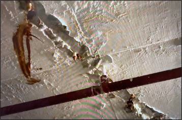
Figure 2 below presents photographs of concrete spalls and accelerated corrosion of rebar in concrete taken at the Champlain Towers South Condominium at high elevation, low elevation, and the swimming pool equipment area.
Figure 3 below contains photographs showing extensive cracking and corrosion of pool deck (the ceiling of the garage).
Figure 4 below presents photographs showing extensive cracking of concrete and peeling of paint due to corrosive moisture penetration on the ceiling of the parking garage.
Figure 5 below is a photograph of cracked concrete due to rebar corrosion from a neighboring condominium.
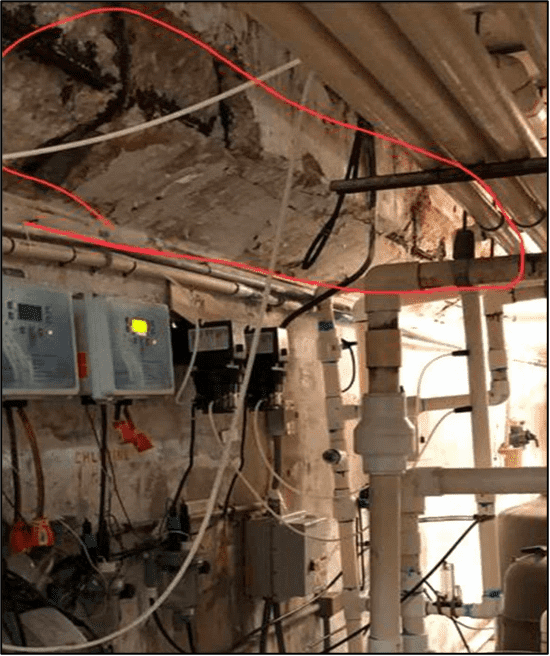
Figure 1: Photograph taken at the Champlain Towers South Condominium collapse site showing extensive spalling and accelerated corrosion of reinforcement.
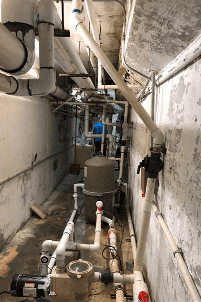
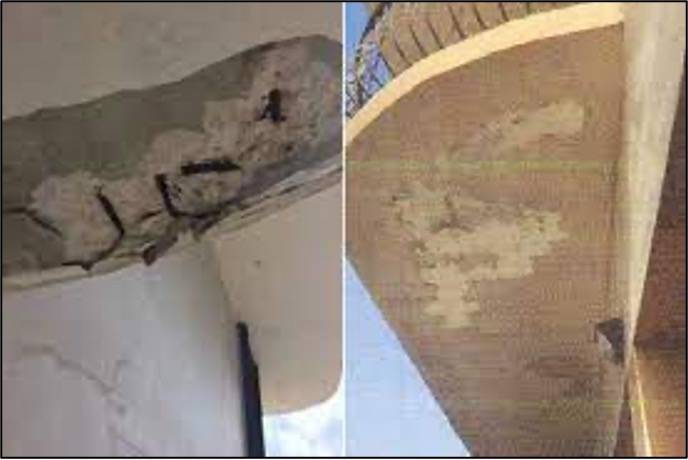
Figure 2: Photographs of concrete spalls and accelerated corrosion of rebar in concrete taken at the Champlain Towers South Condominium collapse site at high elevation, at low elevation, and in the pool equipment room.
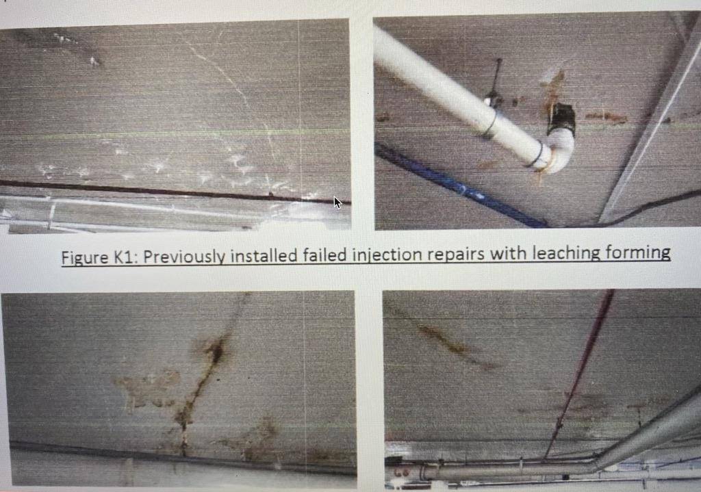
Figure 3: Photographs showing extensive cracking and corrosion of pool deck (the ceiling of the garage).
 .
. 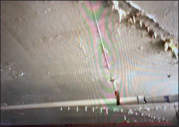
Figure 4: Photographs showing extensive deterioration of concrete, accelerated corrosion cracking of concrete, and peeling of paint due to corrosive moisture penetration.
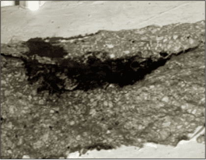
Figure 5: Photograph of cracked concrete due to rebar corrosion from condominium neighboring the Champlain Towers South.
Chlorides and Reinforced Concrete
Figure 6 below presents a 2018 United States Geological Survey map of the approximate inland extent of saltwater at the base of the Biscayne aquifer in Miami-Dade County, Florida [Reference 2]. The area between the shoreline and the red line highlights the saltwater aquifer region, which penetrates substantially at some locations along the shoreline.
As illustrated schematically in Figure 7 below, the salt water slowly penetrated and permeated the concrete and corroded the rebar, reducing the thickness of these critical support structures over a period of years. The disaster was decades in the making.
The photos of the garage flooding do not definitively establish the source of the water. However, what they do show is floodwater, which, based upon prior corrosion engineering expertise, has been happening in the condominium building at lower intensity for many years. It is also further evidence that the collapse was likely caused by cracking and accelerated corrosion. There is reason to believe that groundwater from the water table came up through the floor periodically. This water would contain chlorides.
Evidence is present of accelerated corrosion from corrosive water, or salty water on the ceiling of the parking garage and flooding the parking garage. The collapse started in the lower floors, possibly in the garage area, with crack propagation and the fracture of load-bearing members within the garage through the accelerated corrosion of the rebar and the steel as the primary cause of corrosive water flooding. This needs to be verified by core sampling, profile analysis for chlorides, magnesium and potassium in the cores, and corrosion assessment of reinforcements.
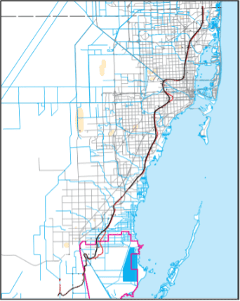
Figure 6: 2018 United States Geological Survey map of the approximate inland extent of saltwater at the base of the Biscayne aquifer in Miami-Dade County, Florida [Reference 2]. The area between the shoreline and the red line highlights the saltwater aquifer region penetrating onshore.
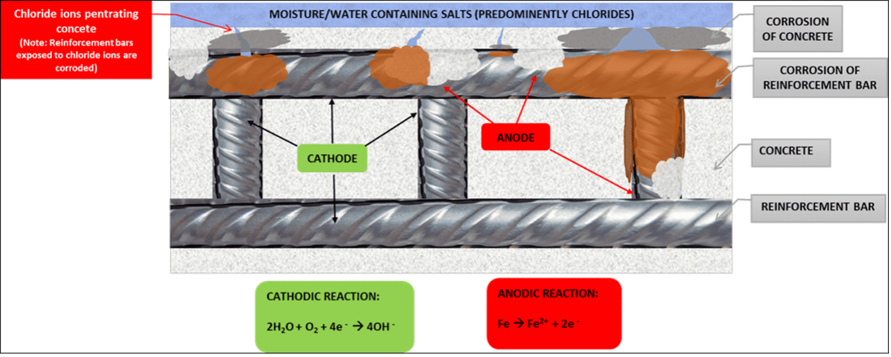
Figure 7: Schematic of chloride (salt) containing moisture penetrating reinforced concrete causing accelerated corrosion of rebar and loss in load-bearing capability due to lack of corrosion control, leading to a shallow concrete cover and water membrane degradation.
The salt in the water made the liquid far more corrosive than municipal tap water. Such critical corrosion narrowed the thickness of the rebar in the pool deck area and causes cracking and fractures, which may have led to the eventual collapse of the building.
A final contributing factor that triggered the collapse may have been a slight movement, or subsidence, in the ground beneath the tower, which the already weakened rebar and load-bearing members could not withstand. Figure 8 below is a photograph showing a major structural crack in the garage’s concrete deck. Was subsidence a primary cause? All potential factors have to be investigated and verified during a root cause investigation by experienced engineers, including corrosion engineers.
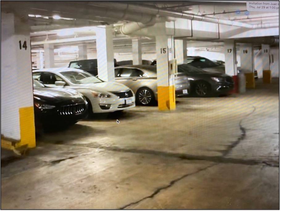
Figure 8: Photograph showing major structural cracks and repairs in garage concrete deck. Did ground movement and subsidence contribute to the collapse? This should be investigated by petrographic analysis, crack morphology, and chemistry profiles of concrete cores taken from both the pool deck and the parking garage slab. The parking garage routinely flooded as evidenced by water lines on concrete.
Previous Inspection
Photographs from the collapse site and a structural engineer’s 2018 survey of the building show accelerated corrosion and less than adequate cover of concrete over the rebar in the garage area, indicating that moisture and salt water had degraded the concrete and corroded the steel reinforcement. The garage was also known to have poor drainage, with residents often complaining about flooding.
The 2018 report by engineer Frank Morabito of Morabito Consulting, Inc. [Reference 3] refers to inadequate waterproofing and inadequate pool deck sloping. It may be that the pool deck area was redone in recent years. An older waterproof membrane may have been replaced with a newer one, or a membrane may have been added as a new item. Cracks with stalactites may have formed many years ago, and a membrane could have been added in recent years to address the cracking problem. This should be confirmed. Note also that the cracked underside of the structural slab is not visible as the ceiling in the garage had been painted over. On page 8 of his report, Morabito says that the crack injection was not done properly. This was probably responsible for the stalactites at the cracks. This also indicates that the structural slab had been repaired once before, and so the current waterproof membrane would not have been present at the end of the original construction. Page 8 of the Morabito report further shows spalling of the garage floor. The Morabito report warned that the failed waterproofing below the pool deck and garage entrance drive area was beyond its useful life and therefore needed to be completely removed and replaced. The report stated that the failed waterproofing was causing major structural damage to the concrete structural slab below these areas, and that failure to replace the waterproofing soon would cause the extent of the concrete deterioration to expand exponentially.
The identification of this failing waterproofing in 2018 also indicates moisture and water being entrapped for many years, potentially flooding under the pool deck for some time. In fact, photos taken less than 48 hours before the collapse by an unnamed contractor in the pool equipment room located in the basement parking garage show extensive concrete spalling and corroded rebar, with the contractor noting there were puddles of water directly beneath the leaking pool deck everywhere in the garage.
Previous reports and inspections were inadequate in that they did not perform corrosion risk assessment, corrosion mapping, or quantification of risks, or offer any low-cost engineering solutions. The reports did not identify all the load-bearing members that exhibited accelerated corrosion or the extent of the corrosion.
It is estimated that accelerated corrosion caused by flooding had likely been going on for 20 to 30 years. Recertification every 40 years is simply not sufficient. Rather, a 15- to 20-year recertification period should be established for the corrosive oceanfront environment. Recertification frequency should be based on corrosivity and ground movement (subsidence) and should include corrosion risk determination.
This accelerated corrosion issue was not picked up because the inspection surveys looked at the structure from a structural engineering standpoint only, and not from a corrosion engineering standpoint. No loss in thickness was measured or corrosion products analyzed. This is not just a structural cracking problem. This is also a serious corrosion problem.
Faulty Repairs on Pool Deck That May Have Had Serious Consequences and Contributed to the Collapse
First Floor Exploratory Demolition – CPR, at the direction of the inspection company Morabito Consulting, performed exploratory demolition at the locations indicated in the Phase IIA contract documents. As illustrated in Figure 9 below, a total of five areas of exploratory demolition were performed (one more area than initially contracted), each approximately 3’x 3’ in size. At the various exploratory locations, the contractor demolished the paver systems (at the pool deck), stamped concrete (in the parking garage/drive aisle) and removed landscaping (within planters down to the existing waterproofing).
Lack of waterproofing under planters: all planters should have had waterproofing due to entrapment of corrosive moisture in C5 environments. Each one should also have had a drain. The thick topping slab may have been associated with previous cracks or delamination due to mechanical damage or accelerated corrosion. The “topping” may have added strength, or not, or been added to cover up “cracks or delamination.” The presence of adequate reinforcement is uncertain from the descriptions in the drawing. This should be verified. Figure 9 below exhibits the specifics of the cores extracted from the site.
a) The tile and mortar were “original” to the area, and were sloped to drains, as per the architect’s plans.
b) The subsequent covering over of that area did not include any sloping to drains; we have seen this stated in an apparently authoritative report.
c) The contractors who did step b did not remove the original tile and mortar (but should have) and did not include sloping (but should have).
d) Those contractors made mistakes, and those mistakes may have had serious consequences.
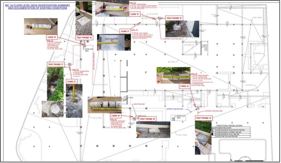
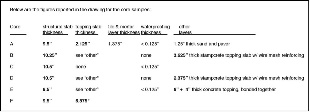
Figure 9: Schematic of the locations of the exploratory demolition and the data collected.
The best explanation for how the slab fell down, with the columns punching through, may be that the top layer of rebar corroded, spalled the concrete, and disbonded the top 2.5 in. of concrete from the rest of the slab! Cores A and B exhibit spalling, which is the dislodgment of small pieces from a slab, most likely due to corrosion of embedded steel.
Construction and Design Issues
Several important design issues that have not been discussed previously need to be considered.
- This is an ISO 12944-2: 2017 [Reference 4] C5 coastal marine (salt water) environment.
- The concrete cover over the rebar was shallow and should have been more than ¾ inch in the absence of corrosion control.
- There appeared to be no slope or adequate drainage for the pool deck, which we believe failed first due to the cracking and accelerated corrosion, triggering the collapse.
- Inadequate repairs had been performed on the pool deck and in the parking garage.
- Extensive cracking in the parking garage ceiling was due to the penetration of corrosive water into the concrete slab.
- No corrosion mitigation, such as cathodic protection, was known to be in place.
What Initiated the Surfside Champlain Towers South Condominium Collapse from a Corrosion Engineering Perspective
We believe that there is a strong possibility that the damage to the building that precipitated the collapse was caused by water damage, accelerated corrosion, and the subsequent degradation of the materials of construction and load-bearing members in the lower floors and parking garage areas of the condominium. This corrosion was likely caused by rainwater that picked up chlorides from airborne salts that had deposited on the building surfaces for years. This saltwater flooded the lower level and parking garage for decades, and permeated the concrete and corroded the steel rebar, reducing the thickness of these support members. Photos from the site show thinning concrete and rebar corrosion in columns in the garage area. A 2018 report found failing waterproofing on the pool deck area, and residents complained of longstanding flooding in the garage. The new video of the moments before the collapse also shows leakage and flooding. The video, posted to TikTok by Adriana Castillero, shows water gushing from the ceiling of the gated garage [Reference 1]. It was filmed at 1:18 am on June 24, 7 minutes before the building collapsed at around 1:25 am. The photograph in Figure 10 below shows the area of the pool deck, with standing water present, which caved in first and resulted in the collapse of the high rise. There were inadequate and faulty repairs on the pool deck. Extensive corrosion damage in the building due to corrosive and salty water was observed, especially in the following locations:
- Pool equipment room.
- Pool deck.
- Garage slab.
- Several load-bearing columns in the parking garage.
- Balconies.
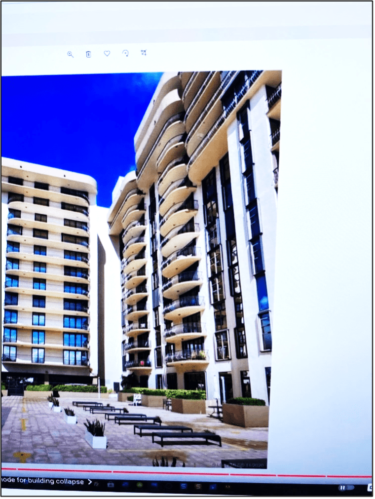
Figure 10: Photograph showing the pool deck near the area of collapse and the presence of standing water.
Figure 11 below presents a drawing of the parking garage and highlights the area in the garage where the collapse is believed to have begun and the pool deck caved in, according to several people at the site at the time of the accident. Figure 12 below present photographs of the collapsed concrete deck, which triggered the partial collapse.
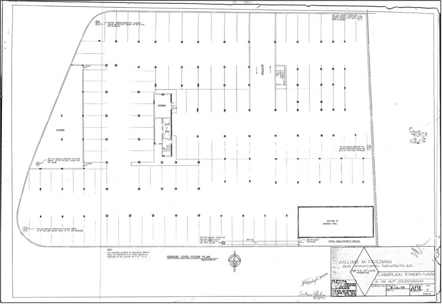
Figure 11: Drawing of the parking garage showing area of initiation of collapse.
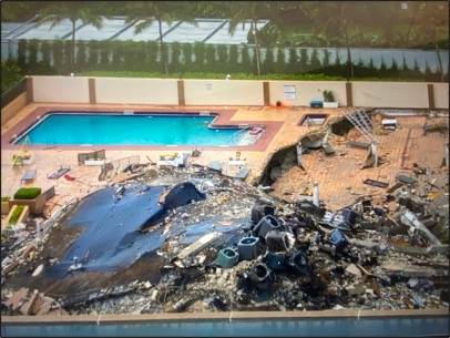
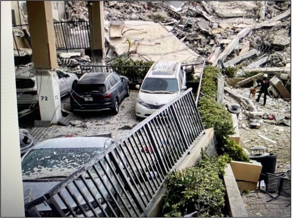
Figure 12: Photographs of concrete deck showing pool deck parking that collapsed, triggering partial collapse (bottom photograph from [Reference 5]. Note parking lot column 72 in the bottom photograph after collapse.
The factors believed to have contributed to the Surfside, Florida Champlain Tower South condominium collapse are:
- Presence of corrosive water on the pool deck for decades. Inadequate cover of concrete over steel rebars.
- Lack of slope for drainage of corrosive water on pool deck for many years.
- Presence of corrosive water in the garage for decades. We saw and there is clear evidence of a water line on several columns in the parking garage, indicating extensive flooding, as shown in Figure 13 below.
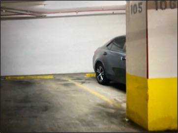
Figure 13: Water line on load bearing column indicating frequent flooding in parking garage.
- Presence of planters that held rainwater, exposing the concrete deck to corrosive water due to inadequate waterproofing membrane and drainage.
- Lack of, or inadequate, waterproofing of pool the deck for decades.
- Inadequate repairs of delaminated areas in the parking garage and the pool deck.
- No corrosion control for reinforced concrete exposed to corrosive moisture.
Figure 14 below presents a photographic timeline of the collapse, courtesy of the UK Daily Mail [Reference 5].
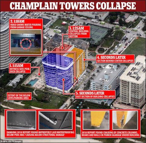
Figure 14: Photographic timeline of the collapse, courtesy of the UK Daily Mail [Reference 5].
Comments on the Causes of the Surfside Condominium Collapse
-
We believe that there is a strong possibility that the damage to the building that precipitated the collapse was caused by the degradation of the construction materials and-load bearing members, itself most likely caused by water penetration and accelerated corrosion in the lower floors and parking garage areas of the condominium.
-
Did Morabito not recommend or engage a corrosion engineering firm to perform a building inspection and corrosion mapping from a corrosion engineering point of view?
-
The previous inspection report(s) are brief and without extensive documentation of the number of columns and beams affected by noted deterioration and their precise locations. There is no corrosion mapping. There is no thickness loss or quantified risk assessment or specific recommendations for corrosion mitigation.
-
Was there to be a more extensive follow-up and more extensive investigation before the collapse?
-
There should have been more photographic documentation of the deterioration of concrete.
-
There are no indications that physical and focused measurements of factors such as the loss in thickness of rebar or the number of load-bearing members exposed to corrosive moisture, flooding, or saltwater (chloride) permeation were performed.
-
There were no measurements of crack widths in the concrete or the petrographic analysis of concrete. No remaining life calculations were performed.
-
There are no documents detailing the intended plans for repair, replacement, or corrosion protection for the structural components that needed them most.
-
9. No in-depth corrosion analysis was performed. Corrosion products should have been analyzed and corrosive ions identified. Chlorides likely played an important role in accelerated corrosion of load-bearing members. A NACE-certified corrosion specialist should have been engaged in the inspections and risk assessment to address corrosion damage related mechanisms and corrosion engineering solutions for this building.
Inspection and Condition Assessment Procedures
The following inspection and condition assessment procedures should be performed immediately on similar aging buildings/structures in nearby C5 and marine environments:
- Pre-assessment: desk study, ground movement assessment, and GIS corrosion mapping of the site.
- Condition assessment and corrosion mapping by half-cell potentials.
- Identification of high corrosion risk sites.
- Direct assessment.
- Thickness loss measurements.
- Quantification of risks by existing models.
- Engineering recommendation: repair, replacement, or no action.
- Cathodic protection and coating after repairs, if feasible and cost effective.
- Post assessment.
Condition Assessment: Corrosion Mapping and Half-Cell Corrosion Potential Measurement
ASTM C876 – 15, Standard Test Method for Corrosion Potentials of Uncoated Reinforcing Steel in Concrete [Reference 6], provides recommended practice for the corrosion mapping and determination of corrosion activity probability of rebar in reinforced concrete structures.
This is performed by placing a reference electrode on the surface of a concrete slab, measuring the electrochemical potential at suitable intervals, and mapping the corrosion activity in the concrete slab. This approach gives an indication of the corrosion risk and accelerated corrosion of steel reinforcement in concrete. The numbers are linked by empirical comparisons to the probability of corrosion activity. Drawing a potential map from the surveyed data will provide and identify both the high corrosion risk areas and low corrosion risk areas. These high corrosion risk areas should be examined for accelerated corrosion and rebar thickness loss.
Concrete Cover Over Steel Rebar
Cover depth determination is carried out to assess conformation with specifications and corrosion risk in corrosive environments. Accelerated corrosion of steel rebar can take place in presence of chlorides if the cover is shallow. This is because moisture, oxygen, and chloride ions will diffuse through the concrete and reach the rebar much faster. This can make a difference of decades in the failure of the reinforced concrete slabs due to corrosion in marine environments. A cover survey, along with a corrosion potential survey, can be performed to construct a corrosion risk map that shows which areas are most susceptible to accelerated corrosion due to low cover. There are low-cost cover meters commercially available to perform this task.
Further, the depth of cover depends upon rebar size. Cover ranges from 3/4 in. for Number 11 and smaller rebar in slabs, joints, and walls, to 1.5 in. of cover for columns and beams, for Numbers 14 and 18 rebar in slabs, joints, and walls. For the Surfside Champlain Towers, the 1.5 in. of cover probably applied
The depth of cover for reinforced concrete in Surfside Champlain Towers South did not meet recommended practice for marine environments because of the permeation of corrosive moisture and corrosive chloride ions. Please note there was no coating or cathodic protection present on reinforcement rebar to mitigate the corrosion due to corrosive and salty water exposure. This is not acceptable from a corrosion point of view, and has contributed to the accelerated corrosion damage observed in the south Champlain Tower due to exposure to water, which was much more severe than in the north tower.
The architects’ written specifications should have provided more detail, and they should have considered the corrosive marine environment in the design for this site.
Chloride Concentration Determination
Chlorides diffuse in concrete and are the primary cause of accelerated corrosion of the rebar. Chloride content and chloride profiles can be measured by procedures outlined in AASHTO T 260-97 (2020), Standard Method of Test for Sampling and Testing for Chloride Ion in Concrete and Concrete Raw Materials [Reference 7]. From a corrosion point of view, the chloride critical values are based on total chloride levels.
Remaining Life Determination
Structural analysis of load-bearing members should be performed with reduced thicknesses and, considering corrosion rate, to determine the remaining life and the need for repair, replacement, or cathodic protection in corrosive salty environments.
Methods and Time Requirements for Corrosion Risk Assessment of Aging Reinforced Concrete
A summary of the methods and time requirements for performing a four-phase corrosion risk assessment of reinforced concrete is provided here.
Phase 1 – Pre-assessment and Pre-survey
Includes a geographical information systems (GIS) mapping and environment classification.
Phase 2 – Indirect Assessment
To be performed by a National Association of Corrosion Engineers/Association for Materials Protection and Performance (NACE/AMPP)-certified corrosion specialist and certified corrosion technicians. The indirect assessment includes the following techniques.
- Visual – 1 m2 per second.
- Sound, Hammer, Chain Tests – 0.1 m2 per second.
- Cover Meter – 1 reading in 5 minutes.
- pH Test – 1 reading in 5 minutes.
- Half Cell – 1 reading in 5 minutes.
- Corrosion Mapping – Several days for large buildings.
- Linear Polarization – 1 reading in 10 – 60 minutes.
- Resistivity – 1 reading in 30 seconds.
- Moisture content of the concrete – one reading in 5 minutes
Phase 3 – Direct Assessment
To be performed by a concrete specialist and a NACE/AMPP certified corrosion specialist. The direct assessment may require several weeks, depending on the complexity and size of the building. It includes the following techniques:
- Petrographic analysis.
- Permeability analysis.
- Loss in rebar thickness measurement.
- Corrosion product chemistry and analysis of deteriorated concrete.
- Remaining life determination.
Phase 4 – Engineering Solution
To be performed by a concrete specialist and NACE/AMPP-certified cathodic protection specialist. The engineering solution includes the following:
- Current requirement testing and CP design – several hours.
- Application of protective coatings – several days. Contractor should apply.
Recommendations for Building Inspection and Condition Assessment
Corrosion risk assessment including electrochemical potential mapping should be performed for condominium tower certifications to look at the thickness of the cover of concrete over the rebars and thickness loss in load-bearing members. This is especially true for buildings on the ocean front, which are at increased risk of such corrosion due to their proximity to the airborne salts from the marine environment.
This was not a one-night event or a sudden failure. Rather, it was a long time in the making because of the accelerated corrosion and loss of thickness. Once the thickness loss reaches a critical point, the failure is catastrophic.
It seems rather apparent that current building regulations in Miami-Dade County, as well as throughout Florida, do not adequately address the serious structural and corrosion concerns that this tragedy has brought to the forefront. Specific inspection and condition assessment recommendations for nearby buildings of similar age are given here.
The on-site inspection and condition assessment should include a detailed investigation of all areas of the reinforced concrete structure, and may require up to several days, depending upon the size of the building. The inspection and condition assessment of the aging structures in ISO 12944-2: 2017 [Reference 4] C5 coastal marine environments such as found in this area should include the following:
- Visual inspection.
- Petrographic analysis – to determine concrete condition.
- Sound test to detect delamination.
- Phenolphthalein – to determine pH and carbonation.
- Chloride content – to identify chloride corrosion risk.
- Linear polarization corrosion rate – to determine direct exposure corrosion rate.
- Continuity test – to determine continuity of rebars.
- Stray current survey – to determine stray current corrosion risks.
- Resistivity – to determine resistivity and corrosion risk of concrete.
- Corrosion mapping by electrochemical and non-destructive testing (NDT).
Concrete core samples should be retrieved from corroded areas (identified in corrosion mapping) for petrographic analysis to determine if the concrete is structurally sound or requires repair or replacement.
As an example, from a prior investigation by the authors, Figure 15 below shows a core sample taken from a building that has been in service for many decades. Corroded rebar can be seen in the photograph. The top piece of rebar has lost nearly half of its thickness. The next photograph in Figure 16 below shows a closeup of the rebar. The flat, thinned section of the rebar can be observed at the top. The corrosion mapping identified this readily.
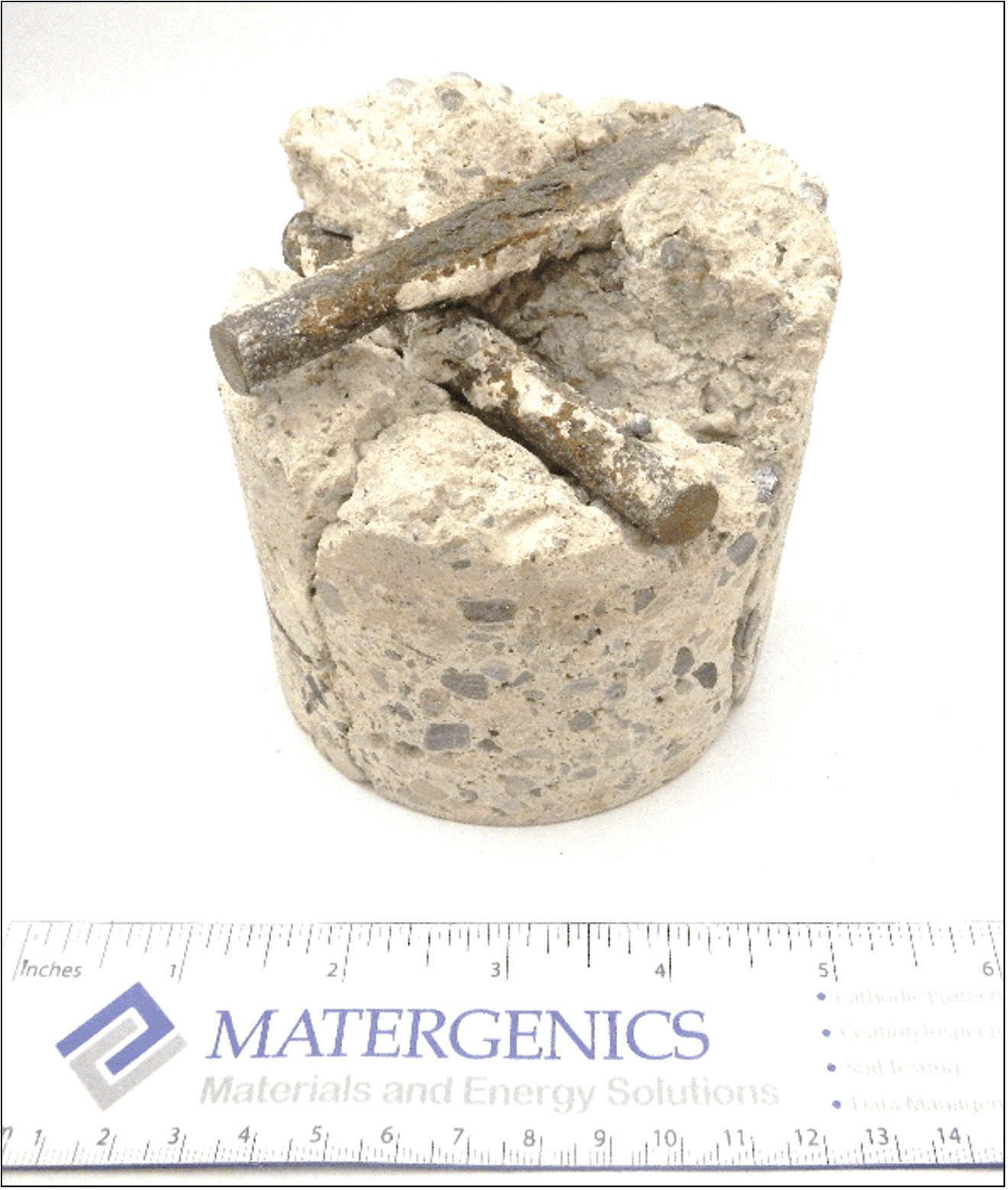
Figure 15: Photograph of core sample from a historic US building, depicting corroded rebar.
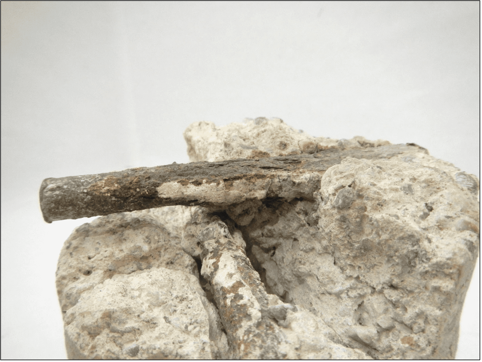
Figure 16: Closeup photograph of the rebar inside core sample, with thickness loss shown at the top. The corrosion risk was captured early on. Corrosion mitigation and cathodic protection prevented catastrophic failure in this 100-year-old building.
Rebar corrodes in the presence of chlorides, which are common in sea water and de-icing salts. Corrosion of rebar can cause reduction in cross-sectional areas, as seen in the photographs above. This loss of thickness can weaken the rebar and cause collapse. Another way that corrosion of rebar can cause concrete failure is through delamination or spalling. A delaminated piece of concrete can be seen in Figure 17 below. Delamination is caused by the formation of iron oxide around the rebar, which results in the expansion in volume of the corrosion products, causing the concrete to spall. This eventually leads to cracking or sections of concrete breaking away from the rebar. Here, the brown/black line shows where the iron oxide was building up.
The condition of the concrete in this previous investigation is like what is believed to be occurring now in Surfside. Both corrosion and delamination have been identified in Champlain Towers South and its neighboring condominiums. These condominiums, being next to the ocean, are exposed to high levels of chlorides that accelerate the corrosion of the steel-reinforced concrete. Previous inspections of these condominiums have not measured the extent of corrosion, nor have they made the urgency of the situation clear to the owners. Immediate action or expedited inspections should be performed in response to corrosion inspections performed by NACE/AMPP-certified corrosion engineers and technicians.
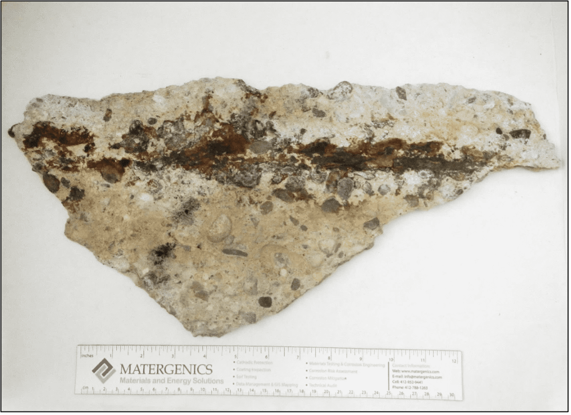
Figure 17: Photograph of rebar corrosion and concrete delamination due to exposure to corrosive water.
Based upon on-site surveying and laboratory analyses results, and employing sound materials and structural engineering principles, determination of the extent of damage and remaining service life should be undertaken. Critical questions to be answered here are the following:
- Is the reinforced concrete structurally sound?
- Does the reinforced concrete require repair or replacement?
Consideration should be given to material selection for repair and/or replacement of the components of the reinforced concrete structure. In addition to concrete repair materials, this will include alternative materials, including non-concrete auxiliary materials and maintenance coatings that may be applied to mitigate corrosion.
Specifically, it is imperative that future regulations require that both corrosion engineering experts and structural engineers take part in building inspections to provide detailed reporting and an exact quantification of corrosion risk in their condition assessments. Condominium associations are also now on notice that they need to take immediate action with respect to corrosion assessment.
In another major case, when Hurricane Dennis blew past the Panhandle in 2005, the Tidewater Beach Resort sustained significant corrosion damage from the wind and rain mixed with sea salts, as well as flooding by rainwater mixed with salt spray from Gulf of Mexico. The authors investigated the case and determined the damage was permanent and would grow in this type of moist C5 environment due to presence of crevices and chloride penetration into reinforced concrete. This could result in accelerated corrosion of reinforcement, weaking of structure and deterioration of construction materials. The developer decided to replace all components exposed to corrosive salt immersion and spray.
Engineering Solution: Coatings and Cathodic Protection
If accelerated corrosion is captured early on, coating application and cathodic protection can mitigate the accelerated corrosion after repairs at low cost.
Coating Application
Consideration should be given to coatings for corrosion mitigation of reinforced concrete structures. However, just coating the concrete will do nothing to mitigate water movement through the structure. Cracks visible on the parking garage ceiling mean that the cracks have penetrated the slab from the top. Therefore, the structural slab must be exposed on the topside and repairs such as grouting the cracks, injecting epoxy, and waterproofing the top of the slab need to be performed.
Cathodic Protection
Cathodic protection is a method wherein enough DC current is continuously supplied to a submerged or buried metallic structure to mitigate, slow down, or temporarily stop natural corrosion processes from occurring. The DC current corrodes a sacrificial anode when it is connected to a structure to be protected. Figure 18 below is a schematic of the general concept of a cathodic protection system for reinforced concrete.
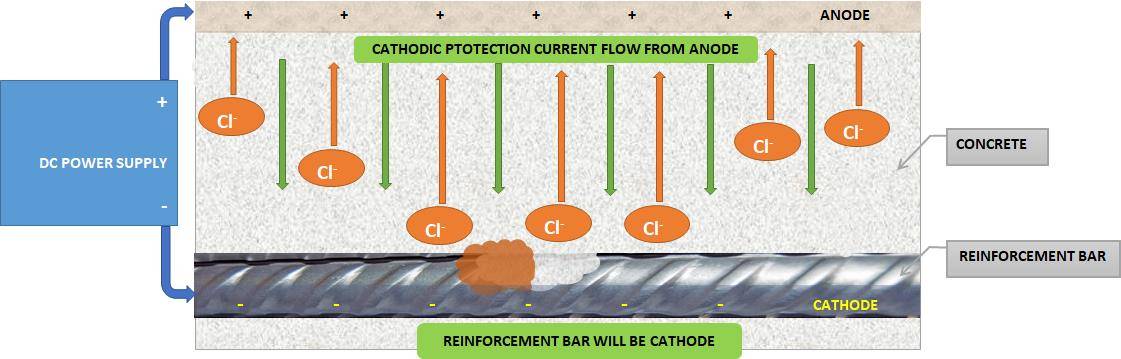
Figure 18: General concept of a cathodic protection system for reinforced concrete.
There are two methods for supplying DC to cathodically protect a structure. They are the following:
- Galvanic or sacrificial anode cathodic protection system (SACP).
- Impressed current cathodic protection system (ICCP).
The galvanic anode cathodic protection system generates DC because of the natural electrical potential difference (electrochemical reaction) between the metal to be protected (cathode) and another metal to be sacrificed (anode). The sacrificed metals such as magnesium (Mg), zinc (Zn), or aluminum (Al) all have a lower and more negative electrical potential with respect to the carbon steel reinforcement. The current output of this system is affected by factors such as:
- Driving voltage difference between the anode and the cathode.
- Resistivity of the electrolyte (environment).
- pH factor.
- Natural or man-made environmental chemistry and/or contaminates.
The impressed current cathodic protection system comprises four main components, which together constitute an electrical circuit. They are as follows:
- A controllable DC power source – usually a transformer rectifier.
- An applied anode – a material placed onto or into the concrete or surrounding electrolyte to enable current
- An electrolyte – normally the pore water present within the concrete, or in the case of remote anodes, also the water, soil, or mud in which the anodes are placed.
- A return electrical path – normally the electrically continuous reinforcement steel to be protected.
Impressed current cathodic protection systems employ the use of electrically forced galvanic reactions to protect steel in an electrolyte such as concrete. Anodes are installed in the concrete in strategic locations near the steel to be protected. A cathodic protection rectifier applies a DC voltage to the system, with the positive lead connected to the anodes and the negative lead connected to the structural steel (cathode). Appendix A presents two important case studies describing the application of impressed current cathodic protection to historical buildings, which are based on a previous publication by the authors [Reference 8]. Appendix B briefly defines and summarizes the various types of deterioration that occur in concrete during service. Appendix C is a listing of published American Concrete Institute (ACI) standards, practices and manuals on concrete corrosion. The ACI is located in Indianapolis, Indiana, and its website is https://www.concrete.org/.
Conclusions
Core samples taken earlier exhibit delamination and spalling, likely due to accelerated corrosion of the rebars in the pool deck slab. Accelerated corrosion of rebar was due to rainwater mixed with chloride deposition on the pool deck for decades. There were reports as early as 1996 of extensive water damage and accelerated corrosion in the pool deck and parking garage. The pool deck and several planters did not have a slope or water drainage. Entrapped pools of water were always observed on both the pool deck and parking garage areas. Spalling of concrete was observed everywhere in the building, including the pool deck and garage slab, indicating accelerated corrosion of rebar and load-bearing members due to corrosive rainwater exposure. This rainwater picked up chloride ions that had been deposited on external surfaces and was entrapped and concentrated on the pool deck. The salt in the water makes the liquid far more corrosive than municipal tap water. Such critical corrosion narrows the thickness of the rebar in the pool deck area and causes cracking and fractures, which may lead to eventual collapse of the building. This saltwater penetrated through the concrete in the pool deck causing accelerated corrosion of the steel reinforcement, delamination and weakening the structural concrete. The disaster was decades in the making. Possible saltwater sources should be investigated by analyzing corrosion products and corrosive ions inside the concrete cores for both pool deck and garage concrete in suspected areas that entrapped corrosive water exposure extensive damage, cracking and spalling. There is evidence of extensive cracking in the pool deck slab (see the videos taken in the parking garage of the ceiling in 2020).
It should be noted there is a record of repairs in 1996 that included repairs due to corrosion of rebars and spalling. No direct or indirect corrosion risk assessment was performed in 1996 or 2018. The extent of corrosion damage and loss in thickness of rebar in pool deck slab was not mapped or determined due to lack of knowledge of corrosion risk. Both engineers and contractors made mistakes, and those mistakes had serious consequences.
In our opinion, lack of knowledge of corrosion damage mechanisms contributed to collapse and failure of the Surfside Champlain Tower South condominium collapse. No corrosion engineers were engaged in the condition assessment or engineering solution from corrosion point of view!
There was extensive cracking and water leakage on the underside of the pool deck over the parking garage. The source(s) of corrosive water in the garage should be investigated further by analysis of corrosion products, analysis of chlorides, and analysis of seawater corrosive ions in the concrete. Concrete petrographic analysis should be performed on pool deck cores in different areas close to the pool and those near parking lot columns, where the failure began. Water table and seawater ingression should also be investigated, as there were major cracks in the garage slab, indicating possible ground movement. This should be investigated by petrographic analysis and chemical profile analysis of concrete cross-sections.
Root cause failure analysis should be performed to verify the failure mechanisms proposed in this paper. Corrosion risk assessment and corrosion engineers should be included in recertification program(s), and the recertification frequency should be based on the corrosivity of the environment and previous inspections.
In conclusion, corrosion risk assessments of load-bearing members and reinforced concrete early on by NACE(AMPP)-certified corrosion engineers may have prevented this catastrophic failure. The 40-year recertification cycle has failed to account for this disaster. The time between certifications should be based on the corrosivity of the environment and the results of previous inspections. Identifying the corrosion risk is only the beginning; determining its severity and responding immediately can prevent disasters and save hundreds, or even thousands, of lives.
The collapse of the Champlain Towers South Condominium in Surfside, Florida may have been caused by deterioration of the reinforced concrete over time, inadequate design, workmanship, faulty repairs, stress overload, or accelerated corrosion due to chlorides in a marine C5 environment. One or more combinations of these factors could have resulted in the progressive failure and eventual collapse of the building. Corrosion is a life limiting mechanism for aging structures. In this paper we discussed the possible mechanisms for collapse of the Champlain Towers South Condominium from a corrosion engineering perspective. The potential for failure from a corrosion point of view has not been widely discussed in the media coverage of the collapse. Not all pertinent photographs or building materials have been examined to a reasonable degree of engineering certainty. Accordingly, this document is subject to change, clarification, or amendments as other material information may be discovered and presented in the future.
References
-
Castillero, A. (2021). Tik Tok video. https://www.youtube.com/watch?v=0g1sNRSOz44. Accessed July 26, 2021.
-
United States Geological Survey (2018). Map of the Approximate Inland Extent of Saltwater at the Base of the Biscayne Aquifer in Miami-Dade County, Florida, 2018, Washington, DC: U.S. Department of the Interior, 2018.
-
Morabito, F. (2018, October 18). Champlain Towers South Condominium Structural Field Survey Report, Report to Maggie Manrara of Champlain Towers South, MC Job # 18217. Morabito Consultants.
-
International Organization for Standardization (2017). ISO 12944-2: 2017, Paints and varnishes – corrosion protection of steel structures by protective paint systems – Part 2: Classification of Environments.
-
Sharp, R. (2021, 1 July). Water filmed pouring into garage of Miami condo minutes before it collapsed is likely part of the flooding and leaks that have corroded the building’s metal and concrete, expert says. The Daily Mail. https://www.dailymail.co.uk/news/article-9746775/Expert-Water-pouring-Miami-condo-garage-flooding-corroded-building-decades.html, accessed July 9, 2021.
-
American Society for Testing and Materials (ASTM) International. (2015). ASTM C876 – 15, Standard Test Method for Corrosion Potentials of Uncoated Reinforcing Steel in Concrete.
-
American Association of State Highway and Transportation Officials. (2020). AASHTO T 260-97 (2020), Standard Method of Test for Sampling and Testing for Chloride Ion in Concrete and Concrete Raw Materials.
-
Zamanzadeh, M., Bayer, G.T., Groll, K., McArdle, S., & Parks, J. (2007). Assessment, selection, and specification of cathodic protection measures in reinforced concrete infrastructures and historic buildings [paper presentation]. CORROSION/2007, Paper No. 07307. Houston, Texas: Association for Materials Protection and Performance (AMPP).
Appendix A
Case Studies for Aging Buildings
Two case studies are presented here in which the authors applied the methodology discussed in this paper [Reference A-1]. They are the Bok Tower at the Bok Tower Historic Sanctuary in Lake Wales, Florida, and the dome of the Utah State Capitol Building in Salt Lake City, Utah.
The Bok Tower
The Bok Tower is one of America’s most unique and beautiful landmarks. The construction of the Bok Tower Historic Sanctuary in Lake Wales, Florida began in 1927 and was completed on February 1, 1929. This historic building is a beautiful tower, and is the focal point of the sanctuary, which houses one of the world’s finest carillons. The tower is 15.5 m2 at the base, changing form at 45.7 meters high to an octagon some 11.3 meters on a side, with sculpture design by Lee Lawrie. It is surrounded by a 4.6-meter moat which serves as a lily pond. Bok Tower’s interior contains the Anton Brees Carillon Library, said to be the largest carillon library in the world.
The case study provides a description of design requirements and installation procedures for an ICCP system for the Bok Tower. The Bok Tower is a masonry-encased steel framed building with marble and coquina siding. Figure A-1 below presents photographs of the Bok Tower. The coquina brick used to cover most of the tower exterior is a porous brick made of crushed seashells and similar material. Corrosion of horizontal structural steel members caused the-coquina brick facade and underlying masonry to separate from the tower.
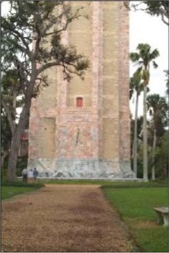
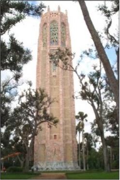
Figure A-1: Photographs of the Bok Tower.
An area of corrosion of the steel reinforcement is shown below in Figure A-2. The root cause of corrosion was found to be ingress of moisture through the porous coquina brick and from openings in the top of the tower. In addition, there were cavities present, some of which were created by plastic sheeting that was installed behind the coquina brick during a previous repair. The cavities served as the primary sites for accelerated corrosion. During recent repairs, the coquina brick and underlying masonry was removed from the front of the horizontal beams and top plate (which is connected to the horizontal beam and supports the coquina brick). The structural steel surfaces were cleaned, coated with a cementious coating, and encased with brick and mortar. New coquina brick was then fitted to the outside. Furthermore, the areas behind the coquina brick at the comers of the tower were completely encased with ASTM C 270 – 19ae1 Type K mortar [Reference A-2].
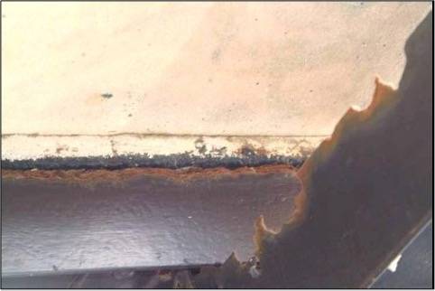
Figure A-2: Photograph of an area of steel reinforcement corrosion in the Bok Tower.
Two onsite visits were performed in the winter of 2006 to explore the feasibility of application of an ICCP system for corrosion prevention of the mortar-encased steel structure. The on-site investigation identified several areas of tower composite wall that may have contained voids due to shrinkage of the mortar. Comparative potential measurements between the surface of the coquina facade and encasing mortar (exposed by removal of the facade) confirmed these observations. Application of temporary titanium anodes and impressed current provided adequate cathodic protection for the masonry-encased steel, indicating cathodic protection was indeed applicable in this situation, provided that the coquina facade is bypassed as it did not serve as a continuous electrolytic path for cathodic protection.
Once it was determined that the structure was fit for application of ICCP, a mock tower section was constructed to help identify design specifics. It was found that most of the structural steel in Bok Tower can be cathodically protected using impressed current cathodic protection and sacrificial anode/coating cathodic protection.
Bok Tower is situated in a moderately corrosive environment. It was found through testing that the steel beams are not actively corroding, likely because of the recent repairs. The masonry was found to be of adequate quality for application of cathodic protection, and the environment was moderately aggressive in that the beams were constantly exposed to moisture and a fresh supply of oxygen. All encased steel members are assumed to be electrically continuous according to schematics and observations. Finally, the steel surface area and total electrical current required to cathodically protect those surfaces was calculated based on onsite and in-house testing. These requirements are discussed below.
Problematic areas on Bok Tower were identified and an ICCP system was designed to protect those areas. The primary areas of concern were identified as the top plate on the horizontal beams and the intersection between the vertical and horizontal beams. Other areas of concern were the web and flange area of the horizontal beams that faced outward as well as the bottom surface of the horizontal beams.
Because of the geometry of the tower and need to preserve the appearance of the exterior, a discrete anode system was designed for the ICCP system, using 11 discrete zones. Use of multiple zones allows for application of different amounts of cathodic protection as needed by each zone. Other systems employ the use of ribbon, wire mesh, or coating anodes. These methods are more invasive, and were found to not be appropriate for use on Bok Tower. The discrete anode system enabled installation of anodes from inside the tower. This allowed for easier installation and preservation of the decorative brick and marble exterior.
Testing and theoretical considerations revealed that the anodes needed to be applied above and below each horizontal beam to apply an adequate current on all exposed surfaces. This array allowed for the target areas of steel to exhibit the 100-mV potential shift required for cathodic protection. The design criteria for the Bok Tower cathodic protection system were provided as follows:
- The approximate steel surface area to be fully protected to the 100 mV potential shift criteria was 143 m2.
- The approximate steel surface to receive cathodic protection for partial corrosion mitigation was 424 m2.
- The maximum required current density under worst-case operating conditions was 10.8 mA/m 2.
- The required current density for normal operating conditions was 2.7 mA/m2.
- The total number of discrete anodes required was 880.
- The total number of reference electrodes required was 43.
As the bell room at the top of the Bok Tower includes openly exposed structural steel, a SACP system employing thermal spray metallizing was selected for this location.
Utah State Capitol Building
The 90-year-old Utah State Capitol Building in Salt Lake City, Utah, was undergoing a renovation and seismic upgrade to extend its life by another century. It is located at the top of State Street and overlooks the Salt Lake Valley. Construction on this great and beautiful building began on December 26, 1912, and the building was dedicated on October 9,1916. The building is 123 m long, 73 m wide, and 87 m from the base of the building to the top of the dome.
Built before seismic-resistant engineering and building codes existed, the Utah State Capitol Building had withstood the loadings over the past 90 years without signs of major structural failure. However, corrosion of steel reinforcement was taking place and required attention.
Concrete served as a base for terracotta panels. Spalling, corrosion, efflorescence, and other problems were occurring in the steel-reinforced concrete in the interior portions of the dome, which was shrouded with an exterior copper roof. Figure A-3 below presents a photograph of the dome.
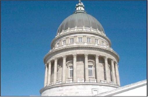
Figure A-3: Photograph of the Utah State Capitol Dome.
As a first step in the selection and specification of a cathodic protection method to be employed in the dome renovation, an on-site corrosion survey and audit of the interior of the dome was conducted. Electrical potential measurements showed the active corrosion of the rebar in many locations. However, continuity testing for the rebar was positive, meaning that a cathodic protection system was viable for this structure. The on-site investigation and preliminary laboratory evaluation revealed that visible internal cracking and steel reinforcement core (rebar) corrosion started at a level just below where the external copper roof ended. Figure A-4 shows a close-up photograph of the rebar corrosion.
After the optimum cathodic protection technique and current for the dome renovation was identified, work was then undertaken to develop and establish the specifications for its installation and operation. Provisions were made for a reference electrode system to monitor corrosion.
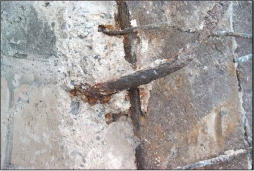
Figure A-4: Photograph of rebar corrosion in the Utah State Capitol Dome.
Before determination of the cause could be made for the deterioration and corrosion of the concrete/steel reinforcement, laboratory petrographic analysis of a sample retrieved on-site was required. Petrographic analysis of concrete cores showed the concrete to be of poor quality because of low alkalinity (carbonation) and a high water/cement ratio, which resulted in a low compressive strength. The high water/cement ratio also produced a very porous concrete. The high alkalinity normally associated with concrete protects embedded steel from corrosion. However, the potential for corrosion of embedded rebar will increase in the presence of low alkalinity, chloride ions and moisture. Chloride ions were found by energy dispersive x-ray (EDS) analysis in the corrosion products collected on site.
It should be noted that some of the submitted core samples exhibited more than 50% loss of thickness of rebar. It was found that cathodic protection would stop further corrosion. However, it would not compensate for load bearing of corroded rebar. Stress calculations needed to be performed to ensure the structural integrity of the reinforced concrete after repairs.
In the second phase of this project, electrochemical studies were performed on the dome concrete and steel reinforcement cores to identify the most suitable cathodic protection technique for corrosion control of the renovated dome. These studies also aided in the determination of current requirements.
Electrochemical laboratory tests were specifically designed to simulate the effect of the practical application of titanium mesh and zinc spray metallized coating as anodes to the renovated (concrete added) inner surface of the Utah state capitol dome. On this basis of lower required current densities, as well as the anticipated greater service lifetime of titanium mesh (40 years) versus zinc metallized coating (10–15 years), titanium mesh was selected as the anode for cathodic protection of the renovated Utah state capitol building dome.
A schematic of the Utah State Capitol Building dome is given below in Figure A-5. Based on discussions with the lead engineering firm on the project, the following characteristics of the Utah state capitol building dome concrete were determined for the purpose of specification of the titanium anode mesh cathodic protection system to be installed:
- Estimates of the minimum and maximum distances of the rebar from the inner surface of the concrete dome.
- Additional concrete thickness added to the dome inner surface for the rehabilitation and the distance of the rebar from the rehabilitated dome inner surface.
- Overall surface area of interior concrete, and surface area of concrete with severe deterioration.
- Surface area of rebar in the existing and rehabilitated concrete dome.
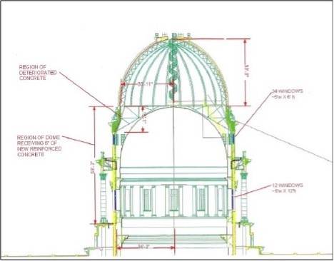
Figure A-5: Schematic of Utah State Capitol Dome showing areas of deteriorated concrete for repair.
The request was to provide cathodic protection on an area totaling 286 m2, and with use of titanium mesh anodes, a corrected minimum anode current, considering contact of steel structural members with concrete, as well as rebar, the total minimum required current was approximately 10 A.
Some guidelines were presented for construction and installation of the cathodic protection system, including the following topics:
- Repair of the damaged concrete in the
- Additional petrographic analysis of the dome concrete.
- On-site testing to verify current requirements.
- On-site testing for verification of the existence of electrical continuity in the steel-bar network in the existing dome structure and in the concrete addition.
- On-site testing to verify discontinuity of rebar with other foreign metallic structures in the dome, including copper roofing
- On-site testing to conduct potential mapping to identify corrosion “hot spots.”
- Installation of reference cells in each section.
- Installation of a predestinated activated titanium mesh in each section.
- Bonding of all sections of the mesh.
- Placement of the concrete overlay.
- Completion of the system electrical wiring.
- Rectifier quantity and placement.
- Startup of the CP system.
- Post-startup and operation monitoring.
The specification covered distributed titanium mesh anodes, which were placed on a blasted, cleaned surface and then covered with a concrete overlay. It was determined that AMPP (formerly NACE) Standard SP0290-2007, Impressed Current Cathodic Protection of Reinforcing Steel in Atmospherically Exposed Concrete Structures [Reference A-3] should always be followed.
The approved anode system was a titanium mesh anode system. Titanium mesh anodes systems consist of expanded titanium mesh coated with a precious metal oxide catalyst that is fastened to a prepared surface and overlaid with concrete to provide a new riding surface. These systems are designed and installed such that the average current density at the surface of the anode does not exceed 110 mA/m2.
The titanium mesh anode recommended may be either one of two types: an anode with a current rating of 24 mA/m2, or an anode with a current rating of 40 mA/m2.
Several material and construction and installation-related specifications were covered. Some important points that should be noted are:
- All wiring must be done in conformance with the latest version of the proper electrical codes.
- Titanium mesh anode must not contact any existing steel structure, rebar, or anchors.
- Titanium mesh is divided into four independent anode units, or electrical zones, employing one rectifier with four terminals. The rectifier should be autopotential- and IR-compensated. The rectifier should be rated at 20 A and 100 V. A minimum of eight reference electrodes should be employed, with a minimum of two reference electrodes per zone.
- Titanium ribbons should be welded to mesh in vertical and horizontal directions; the lead to the titanium wire should be connected to the positive terminal of the rectifier.
- Prior to installation, on-site testing must be performed to verify theoretical calculations and to confirm discontinuity between the rebar and the copper roof and other steel structural members.
- • Consideration should also be given to perform petrographic analysis on other parts of the dome to test the integrity of the concrete and make sure these sections do not exhibit carbonation or accelerated corrosion of the rebar.
Appendix A References
A-1. M. Zamanzadeh, G.T. Bayer, K. Groll, S. McArdle, & J. Parks. (2007). “Assessment, Selection, and Specification of Cathodic Protection Measures in Reinforced Concrete Infrastructures and Historic Buildings,” CORROSION/2007, Paper No. 07307, Houston, Texas: Association for Materials Protection and Performance (AMPP), formerly National Association of Corrosion Engineers (NACE), 2007.
A-2. American Society for Testing and Materials (ASTM) International. (2019). ASTM Standard C270 – 19ae1, Standard Specification for Mortar for Unit Masonry.
A-3. Association for Materials Protection and Performance (2007). AMPP Standard SP0290-2007, Impressed Current Cathodic Protection of Reinforcing Steel in Atmospherically Exposed Concrete Structures.
Appendix B
Types of Concrete Deterioration
Appendix B briefly defines and summarizes the various types of deterioration that occur in concrete during service.
- Corrosion of embedded steel. Embedded reinforcing steel (rebar) is widely used to give concrete greater strength and even flexibility. If the steel corrodes, then the expansion of the corrosion products will cause cracking and spalling of the concrete. Normal concrete is very alkaline, and will therefore cause passivation of any embedded steel. If the concrete loses its high pH, it will no longer offer protection to the steel. Some factors that can lead to steel reinforcement and subsequent spalling include:
-
- Chlorides from admixtures, unwashed aggregate, deicing salts or seawater accelerate corrosion.
- Permeable concrete is more affected.
- Carbonation and depth of concrete cover.
- Cracks that extend to the rebar.
- No corrosion risk if electrical resistivity greater than 50 – 70 x 103 ohm cm.
- Want less than 0.6-0.9 kg Cl-/m3 of concrete.
- Spalling is the dislodgment of large or small pieces from a structure. The dislodged pieces often have a conical or bowl shape. Spalling can result from impact, fire damage, or corrosion of embedded steel.
- Shrinkage cracking. During the curing of new concrete, the moisture within the concrete will diffuse to the surface, where it will evaporate. The concrete on the exterior surfaces will dry and shrink faster than the concrete deeper within the structure, resulting in tensile stresses at the surface which, if great enough, cause the formation of drying shrinkage cracks. Geometry can also affect formation of shrinkage cracking, with long spans between joints being most prone to cracking.
- Carbonation. In older concrete structures, carbonation occurs at the exterior surfaces. The process of carbonation will cause the carbonated surface layer to shrink and crack. Cracks from carbonation tend to be shallower than cracks from initial drying shrinkage.
o Reaction of surface cement paste with moisture and carbon dioxide in environment.
o Lowers pH and effects the passivation of embedded steel and makes corrosion of steel more probable.
o Occurs at surface or along cracks.
o Looks yellow in petrographic cross-sections.
o Also revealed using phenolphthalein pH indicator solution – pH 9. - Freeze thaw damage (frost damage). Concrete is an inherently porous material, although permeability can vary between different structures. The original water-to-cement ratio is largely responsible for the degree of permeability. When water within the concrete pores is exposed to temperatures below 32 °F, this water can freeze, and the expansion in volume caused by the formation of ice will exert an internal hydraulic pressure on the cement matrix, which can initiate internal cracking. Over time and with multiple exposures to freezing temperatures, the internal cracks will grow and the cement matrix will begin to crumble. Water-saturated concrete is most susceptible to freeze thaw damage. The intentional air entrainment of the cement matrix is typically done to prevent freeze thaw damage.
- Pop-outs. Pop-outs are small, localized pits in a concrete surface usually caused by the fracturing of a susceptible aggregate just below the surface. The susceptible aggregates are often sedimentary rocks, which are inherently weak and prone to moisture absorption. The mechanism of freeze thaw causes the formation of pop-outs.
- Salt damage. If dissolved salts are present in the water to which the concrete is exposed, these salts may be absorbed into the concrete, where they crystallize and precipitate out of solution. The volumetric expansion caused by crystal formation may result in internal cracking, eventually leading to disintegration and surface scaling of the concrete.
- Sulfate attack. Groundwater and seawater usually contain sulfates, and higher concentrations of sulfates can often be found in industrial wastewaters and mine-waters. Sulfates can chemically attack the cement matrix of the concrete, leaving behind a soft, powdery surface. On other occasions, sulfate attack can result in the formation of compounds that cause expansion and spalling of the concrete.
- Erosion. Erosion is the progressive deterioration of the concrete surface resulting from high-velocity water flow, cavitation damage in flowing water systems, and mechanical scouring and abrasion by ice, sand and gravel, or other solid materials.
- Structural cracking. Structural cracking results from external loads imposed upon the structure. Direct impact or earthquakes can cause cracking. These cracks tend to be wide and deep. Differential settlement of a structure can cause cracking. Flexural loading can result in fatigue cracking.
- Efflorescence – Water movement through hardened concrete can result in internal leaching. Calcium ions are dissolved and transported to the surface. At the surface, the reaction of the leachates with carbon dioxide in the air and drying of the deposits can result in whitish colored encrustations. The process is known as efflorescence. Efflorescence often occurs at cracks in the concrete. Internal crystallization can weaken the concrete.
o White exudations from cracks.
o Conversion of calcium hydroxide to calcium carbonate.
o Results from excessive moisture content of concrete.
o Can result from either moisture ingress or moisture transmission.
o Condition promoted by porous concrete.
o Moisture can cause spalling.
- Vegetation in cracks. Cracks in concrete that fill with dirt and moisture can sometimes promote the growth of vegetation within the cracks. As the plant roots propagate into the cracks, they can promote further crack propagation and weaken the structure.
- Alkali-aggregate reaction. The original cement used in the concrete mix can often contain alkali ions such as sodium and potassium. Alternatively, these ions can be introduced from the environment or even be present in the aggregates or from an admixture. Certain types of amorphous silica aggregates, or aggregates containing amorphous silica, are susceptible to chemical reactions with the alkali ions. The resulting reaction products will swell in the presence of moisture, leading to internal cracking, which will eventually be visible at the surface as map cracking.
o Alkalis from cement should be less than 0.6% of total cement content.
o Alkalis from unwashed aggregates such as sand.
o Susceptible aggregates are amorphous or microcrystalline silica, such as opal, obsidian, cristobalite, tridymite, chalcedony, chert, or some volcanic rocks.
o Susceptible aggregates react with calcium hydroxide, absorb moisture, and swell, causing cracking.
Appendix C
American Concrete Institute (ACI) Standards, Practices and Manuals on Concrete Corrosion
The following is a listing of published American Concrete Institute (ACI) standards, practices and manuals on concrete corrosion. The ACI is located in Indianapolis, Indiana, and its website is https://www.concrete.org/.
C-1. ACI PRC-201.2-16, Guide to Durable Concrete.
C-2. ACI PRC-212.3-16, Report on Chemical Admixtures for Concrete.
C-3. ACI PRC-222-19, Guide to Protection of Metals in Concrete Against Corrosion.
C-4. ACI PRC-222.2-14, Report on Corrosion of Prestressing Steels.
C-5. ACI PRC-222.3-11, Guide to Design and Construction Practices to Mitigate Corrosion of Reinforcement in Concrete Structures.
C-6. ACI PRC-364.14-17, TechNote: Section Loss Determination of Damaged or Corroded Reinforcing Steel Bars.
C-7. ACI PRC-423.4-14, Report on Corrosion and Repair on Unbonded Single-Strand Tendon Systems.
C-8. ACI PRC-423.8-10, Report on Corrosion and Repair of Grouted Multistrand and Bar Tendon Systems.
C-9. ACI PRC-533.5-20, Guide for Precast Concrete Tunnel Segments.[/vc_column_text][/vc_column][/vc_row]